Construction & Engineering · Updated October 6, 2026
What software do engineers use to mark up and measure PDF drawings?
Reviewed for technical accuracy by licensed professional engineers.
Short answer
Engineering drawing PDF software marks up technical drawings with precision, measures calibrated geometry, extracts engineering parameters from the sheet, and computes section properties — centroid, moments of inertia, polar moment, gyration — on enclosed regions. PDFDepth does all of it in the browser: snap-to-linework markup and dimensioning commands, per-view calibrated measurement, AI extraction of engineering parameters, and export to Excel or CSV.
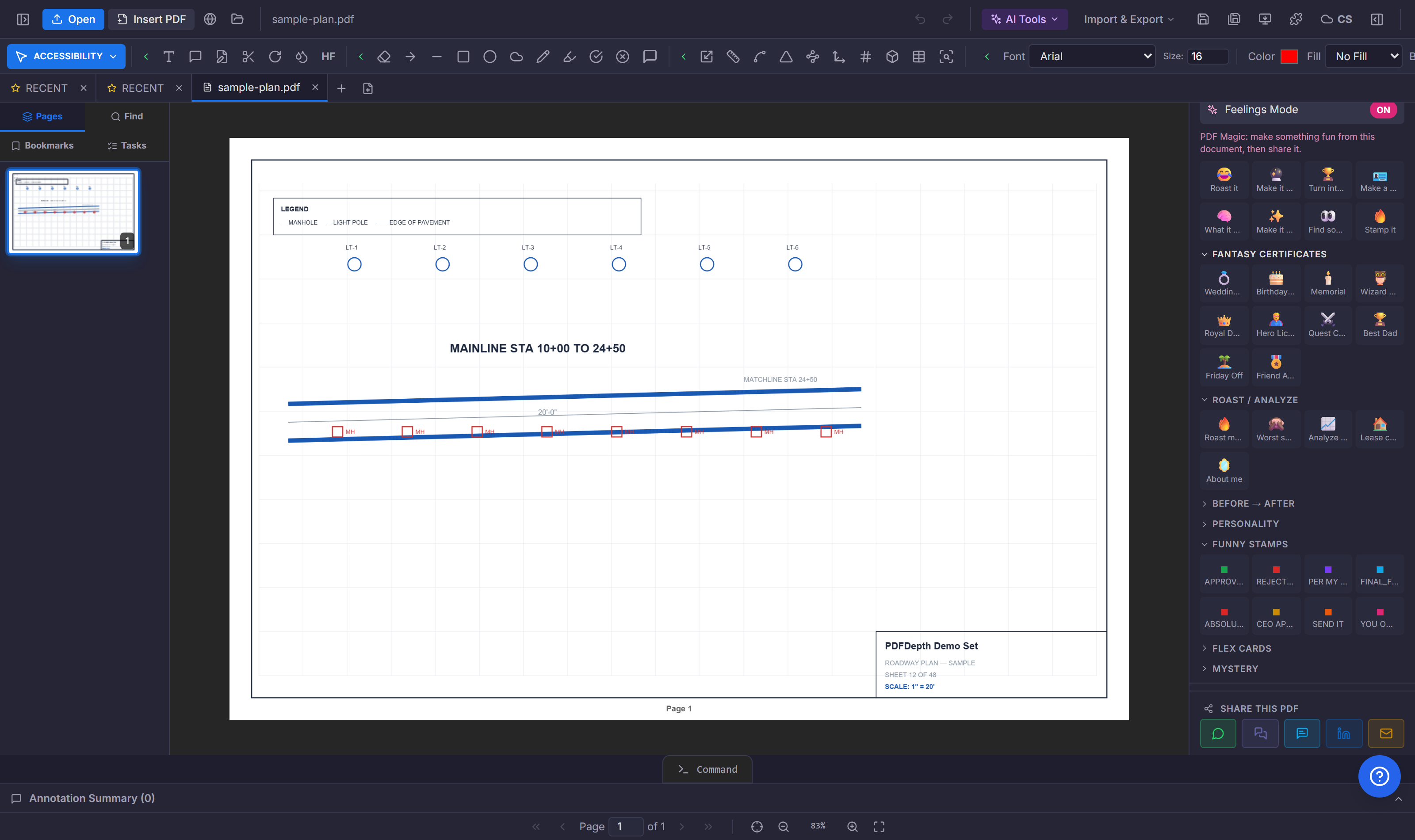
Markup at drawing precision
Engineering markup is not "draw a circle around it." Leaders snap to the feature they reference. Dimensioning commands — DIMLINEAR, DIMALIGNED, DIMRADIUS — add real measured annotations, not guessed callouts. The CAD command line (LINE, PLINE, OFFSET, TRIM, HATCH) adds geometry to the sheet itself, and the smart-trace overlay recolors linework to show a proposed change against existing work.
Measurement and section properties
Calibrated measurement handles distance, area, perimeter, and volume. For an enclosed region, the section-properties tool computes the values a structural or mechanical check needs: centroid, Ix, Iy, polar moment J, and radii of gyration — without redrawing the section in analysis software. Per-view calibration means a detail at a different scale on the same sheet measures correctly.
Extracting parameters from the sheet
A drawing carries data in its callouts: pipe sizes, member designations, voltage ratings, fire ratings. AI parameter extraction reads the sheet and pulls those values into a table — the pipe schedule, the beam list, the fixture count — exportable to Excel or CSV. On a scanned sheet, OCR reads the callout text first so nothing is skipped.
From drawing to deliverable
The marked-up drawing is the deliverable. Flatten it for the record, sign it with a certificate-based digital signature, and share it as a tracked smart link — or export the geometry to DXF for the CAD side. The PDF is where the review happens; the export is what goes back to design.
| Property | Symbol | Use |
|---|---|---|
| Area | A | Material quantity, load area |
| Centroid | C | Neutral axis, load centroid |
| Moment of inertia | Ix, Iy | Bending stiffness |
| Polar moment | J | Torsional stiffness |
| Radius of gyration | r | Buckling / slenderness |
References
Everything in this article runs in the live PDFDepth workspace — the same app the workflows above were verified against.
Key takeaways
- Dimensioning commands (DIMLINEAR, DIMALIGNED, DIMRADIUS) add measured annotations.
- Section properties — centroid, Ix/Iy, J, gyration — compute on an enclosed region.
- AI parameter extraction pulls schedules and callouts into Excel/CSV.
- Per-view calibration keeps details at different scales measuring correctly.
Related questions
Yes — PDFDepth computes centroid, moments of inertia, polar moment, and radii of gyration on a calibrated enclosed region, without redrawing in analysis software.
Do it in PDFDepth
In the app: Left panel → Tools → Measure; Ctrl+9 CAD command line
Try it free — no signup, no upload
Related articles
Put it into practice
Everything above runs inside the PDFDepth workspace — free for 14 days, no credit card.
Start for Free